Introduction
Gigabit Ethernet allows network transfers up to 1.000 Mbps using standard Cat 5 UTP (unshielded twisted pair) cabling. How can this be accomplished, since Cat 5 cables can run only up to 100 Mbps? We will explain this and also other very interesting issues regarding Gigabit Ethernet performance.Ethernet Cat 5 cables have eight wires (four pairs), but under 10BaseT and 100BaseT standards (10 Mbps and 100 Mbps, respectively) only four (two pairs) of these wires are actually used. One pair is used for transmitting data and the other pair is used for receiving data.
Pin
|
Color
|
Function
|
1
|
White with Green
|
+TD
|
2
|
Green
|
-TD
|
3
|
White with
|
+RD
|
4
|
Blue
|
Not Used
|
5
|
White with Blue
|
Not Used
|
6
|
-RD
| |
7
|
White with Brown
|
Not Used
|
8
|
Brown
|
Not Used
|
Ethernet standard uses a technique against electromagnetic noise called cancellation. As electrical current is applied to a wire, it generates an electromagnetic field around the wire. If this field is strong enough, it can create electrical interference on the wires right next to it, corrupting the data that were being transmitted there. This problem is called crosstalk.
What cancellation does is to transmit the same signal twice, with the second signal “mirrored” (inverted polarity) compared to the first one, as you can see in Figure 1. So when receiving the two signals, the receiving device can compare the two signals, which must be equal but “mirrored”. The difference between the two signals is noise, making it very simple to the receiving device to know what is noise and to discard it. “+TD” wire standards for “Transmitting Data” and “+RD” wire standards for “Receiving Data”. “-TD” and “-RD” are the “mirrored” versions of the same signal being transmitted on “+TD” and “+RD”, respectively.

Figure 1: Cancellation technique.
Data Transmission
On 10BaseT standard each bit that the computer wants to transmit is physically coded into a single transmitting bit, i.e., for a group of eight bits being transmitted, eight signals will be generated on the wire. Its 10 Mbps transfer speed means that its clock is of 10 MHz, but just because each clock cycle a single bit is transmitted. On other standards this is different.100BaseT uses a coding scheme called 8B/10B, where each group of eight bits is coded into a 10-bit signal. So, differently from 10BaseT, each bit does not directly represents a signal on the wire. If you make the proper math, with a 100 Mbps data transfer rate, the clock rate of 100BaseT is of 125 MHz (10/8 x 100).
So, Cat 5 cables are certified to have a transmission speed of up to 125 MHz.
What Gigabit Ethernet does is to change the coding. Instead of making each bit to be coded into a single signal like 10BaseT or to code each 8-bit group into a 10-bit signal, it codes two bits per signal. So, a signal over a Gigabit Ethernet cable represents two bits, instead of a single bit. In order words, instead of just using two voltages on a signal representing merely “0” or “1”, it uses four different voltages, representing “00”, “01”, “10” and “11”.
Also, instead of using just four wires of the cable, Gigabit Ethernet uses all wires.
On top of this, all pairs are used in a bi-directional fashion. As we’ve seen above, both 10BaseT and 100BaseT uses different pairs for transmission and reception; on 1000BaseT, as Gigabit Ethernet cabling is also called, the same pairs are used for both data transmission and reception.
The beauty of Gigabit Ethernet is that it still uses the 100BaseT/Cat 5 clock rate of 125 MHz rate, but since more data is transmitted per time, the transfer rate is higher. The math is quite simple: 125 MHz x 2 bits per signal (i.e., per wire pair) x 4 signals per time = 1.000 Mbps.
This modulation technique is called 4D-PAM5 and it actually uses five voltages (the fifth voltage is used for its error-correction mechanism).
So it is a mistake to say that Gigabit Ethernet runs at 1.000 MHz. It doesn’t. It runs at 125 MHz just like Fast Ethernet (100BaseT), but it achieves a 1.000 Mbps because it transmits two bits per time and uses the four pairs of the cable.
In the table below you can check Gigabit Ethernet cabling pinout. “BI” stands for bi-directional, while DA, DB, DC and DD stand for “Data A”, “Data B”, “Data C” and “Data D”, respectively.
Pin
|
Color
|
Function
|
1
|
White with Green
|
+BI_DA
|
2
|
Green
|
-BI_DA
|
3
|
White with
|
+BI_DB
|
4
|
Blue
|
+BI_DC
|
5
|
White with Blue
|
-BI_DC
|
6
|
-BI_DB
| |
7
|
White with Brown
|
+BI_DD
|
8
|
Brown
|
-BI_DD
|
Performance Issues
Nowadays several motherboards come with one on-board Gigabit Ethernet port. Some very high-end motherboards can even provide two Gigabit Ethernet ports. Depending on motherboard architecture, however, the Gigabit Ethernet may not achieve its 1.000 Mbps transfer rate.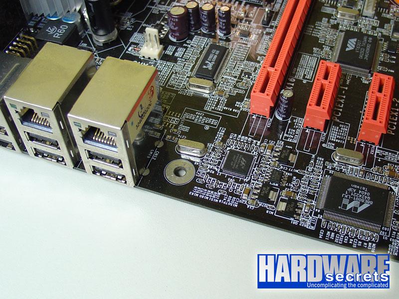
Figure 2: Two Gigabit Ethernet ports and chips on DFI LanParty 925X-T2.
PCI Express, on the other hand, has a maximum transfer rate of up to 250 MB/s and is a point-to-point connection, which means that it doesn’t share this 250 MB/s bandwidth with any other device, thus allowing Gigabit Ethernet to achieve its full speed.
How can one tell which bus Gigabit Ethernet chip is connected to? There are three basic ways. The easiest way is to see if your motherboard is based on PCI Express bus. If it doesn’t, the Gigabit Ethernet chip can only be connected to the standard PCI bus.
The second way is to take a look at the motherboard manual or the motherboard specs page on the manufacturer's website and look for this information there. Usually on the main specs page it is written “PCI” or “PCI Express” besides the name of the Gigabit Ethernet controller, telling you which bus is used.
The third way is to go to the Gigabit Ethernet controller manufacturer website (VIA, Marvell, 3Com, etc) and look for the main specs for the model used on your motherboard. The bus type should be discriminated there.
To give you a real example, let’s take a look at the Gigabit Ethernet chips used in Figure 2. One is a Marvell 88E8001, which is PCI, and the other one is a Marvell 88E8053, which is PCI Express.

Figure 3: One of the Gigabit Ethernet chips used on DFI LanParty 925X-T2 (Marvell 88E8001).
Source "HARDWARE secrets"
click here download it as PDF file


No comments:
Post a Comment